
Download: RaffaelloBonghi-PhDThesis.pdf
ARVI is composed of three movable elements and two tracks fixed to the robot base by hinges and a system of springs to assure dumping and reduce vibrations during the displacements in the machine. In addition, the rover is equipped with a motorized camera, remotely driven, for visual inspection and to provide a visual feedback signal for autonomous navigation.
The platform has also been equipped with a recovery system for tile found inside the room; such a system is particularly complex because of its small size; the prototype needed to use a 3D printer to realize the recovery of the crank mechanism. The latter provided with camera and motors to be automated and allow recovery in the autonomy of the tile. The dimensions are 28 cm width, 26cm depth, and 7cm height.
Robot conception
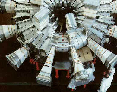
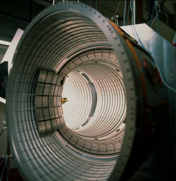
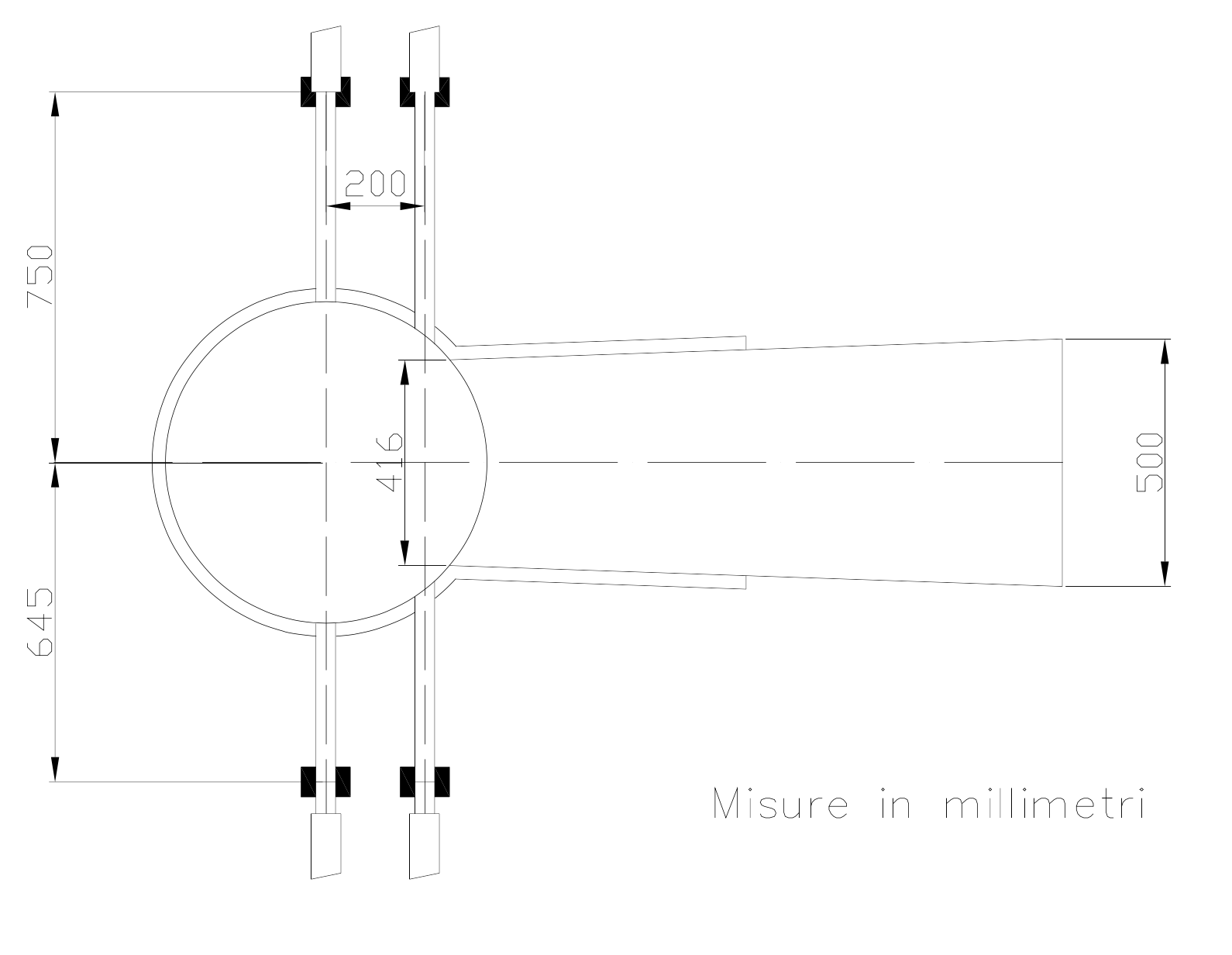
The FTU section and profile measures have been the base for the design of a mechanical frame and type of “wheel” to sliding in the toroidal pipe.
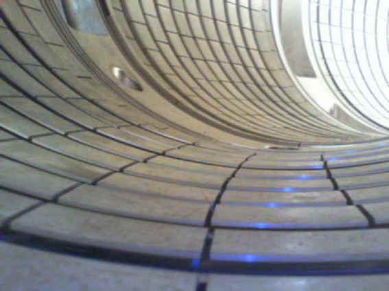
The section compares to other Tokamak machines in FTU have a circular shape; with this configuration, it is choice a tracked design. Inside the vacuum vessel, a track can slide over all holes, and if a technician required a separate inspection to see a spot when ARVI is climbing the vacuum vessel. Compare with a wheeled mobile platform, a tracked platform does not slide in a pipe and is more stable when crossing a hole, but the length of the track must have a dimension major than the maximum height inside the chamber.
The tracks in the mobile robot are connected to the base frame with one or more hinges. This new degree of freedom put the track surface entirely in contact with a circular section in the vacuum vessel. This tricky option reduces the power consumption for the tracks motor and keeps more stable the mobile platform when the robot is sliding.
In ARVI, was chosen to the power supply with an external cable. Without batteries and power regulators, the robot is lightweight and does not have a mechanical complication, only to select a point in the chassis were put the power plug. In addition with the power supply cable is added other two lines. The thread contains a wire communication with the internal electronic components, the mini PC and the motor control board, and the last cable to sustain the mechanical frame when the robot is moved inside from the gate. This cable is in marine steel and has another functionality when the robot is at fault, and the technician retrieves the robot inside the chamber.
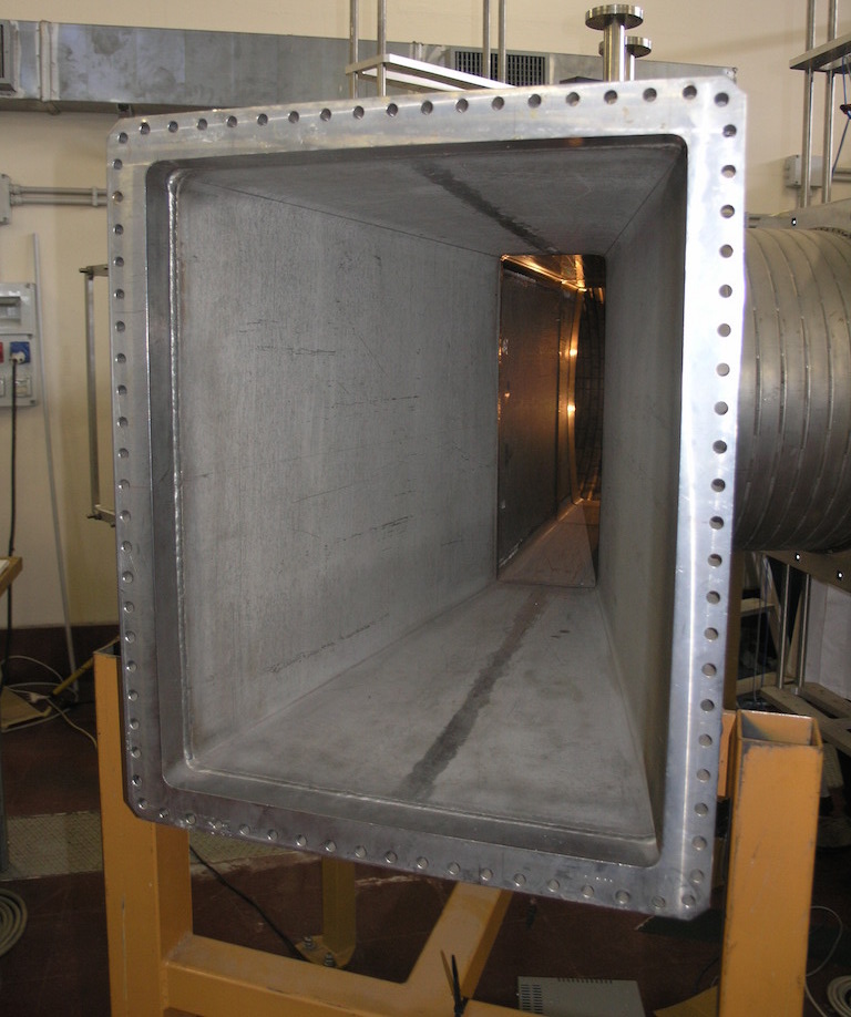
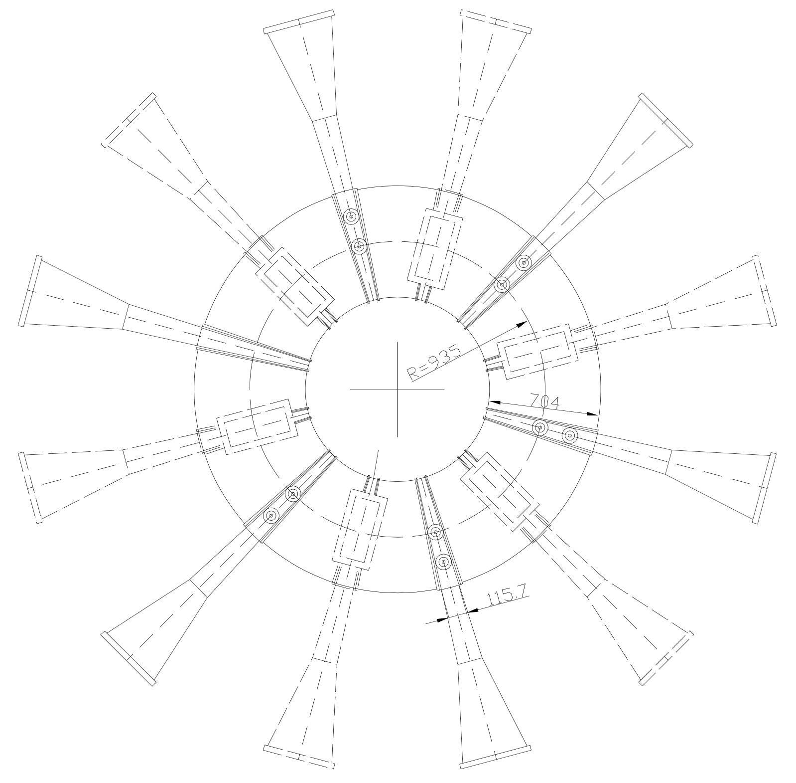
ARVI does not enter autonomously inside the chamber because the gate has a short width. In the table below are collected the gate’s size in the FTU, in the figure above. This issue has been solved by insertion with the manipulator FARM with a specific end-effector inside the robot ARVI. When the robot sliding in the chamber, unroll all cables inside the end-effector.
Usually, the FTU vacuum vessel is fully dark, and it is required to see in the camera with one or more lights. This issue is solved with one or more high luminance LEDs. A LED has a low power consumption, but it has high performance.
| FTU tokamak parameters | value | dim. |
|---|---|---|
| Tokamak radius | 935 | mm |
| Section radius | 310 | mm |
| Gate width | 115.7 | mm |
| Gate height | 416 | mm |
| Hole width | 30 - 70 | mm |
| Hole max height | 390 | mm |
Limiter tiles
In the vacuum vessel, the FTU uses a block of tiles to confine plasma during a reaction. A Block with 30 tiles arranged with 5 x 6 with a weight of 18Kg. Usually are removed and substitute with an IVROS robot, but this robot must remove only in the block.

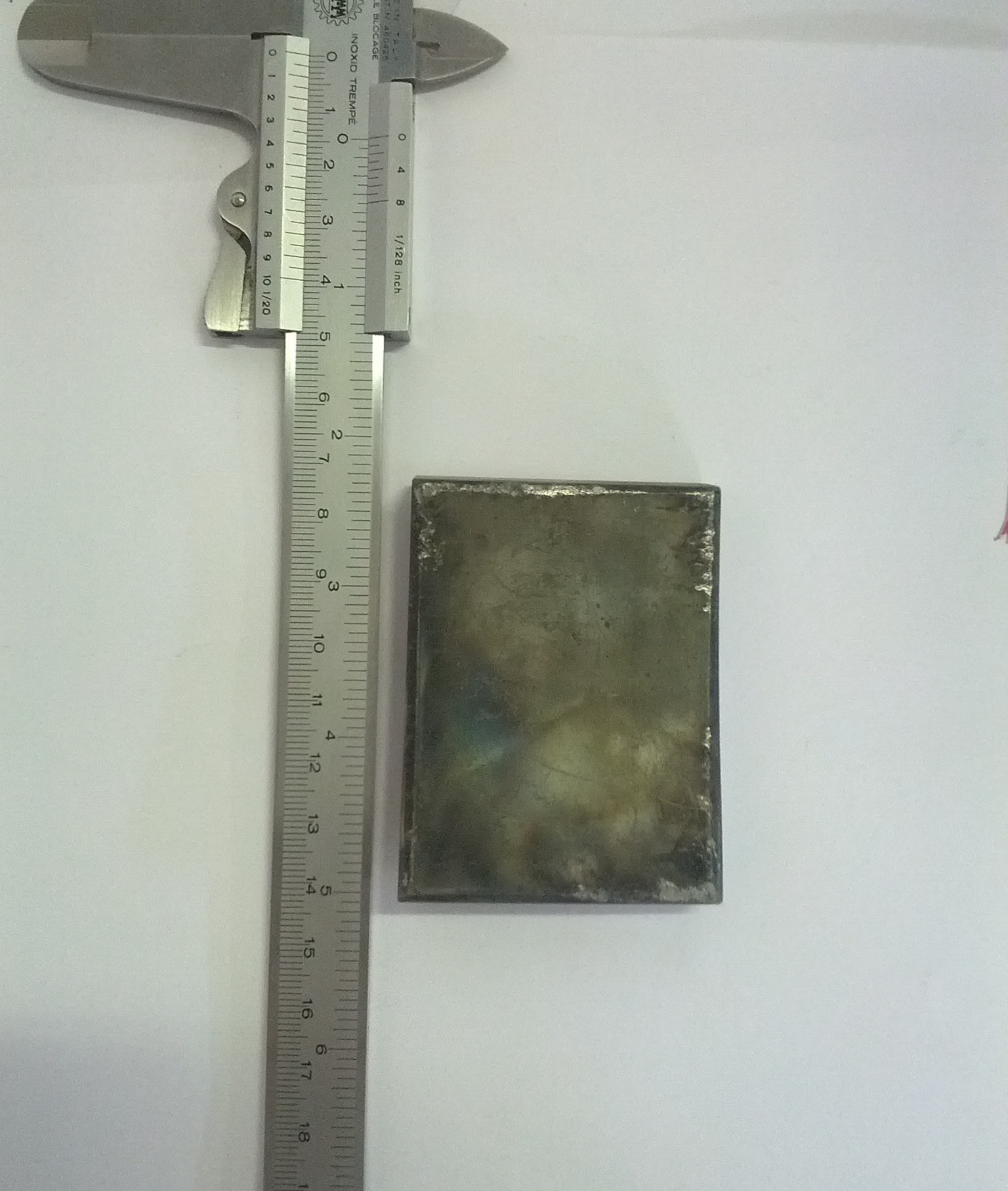
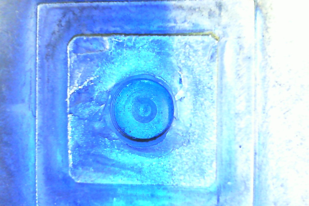
A limiter tile is a parallelepiped block in tungsten where it is placed in the center of large size another block with a hole thread with a length of $d = 4mm$, in the figure above. All tiles are mounted in a particular frame and are fixed in support on the first wall in the vacuum vessel. In table 5.2 are collected all information about tile size and position of box and hole thread.
| FTU Limiter tile | value | dim. |
|---|---|---|
| width | 100 | mm |
| height | 40 | mm |
| box length | 10 | mm |
| hole thread | 4 | mm |
ARVI History
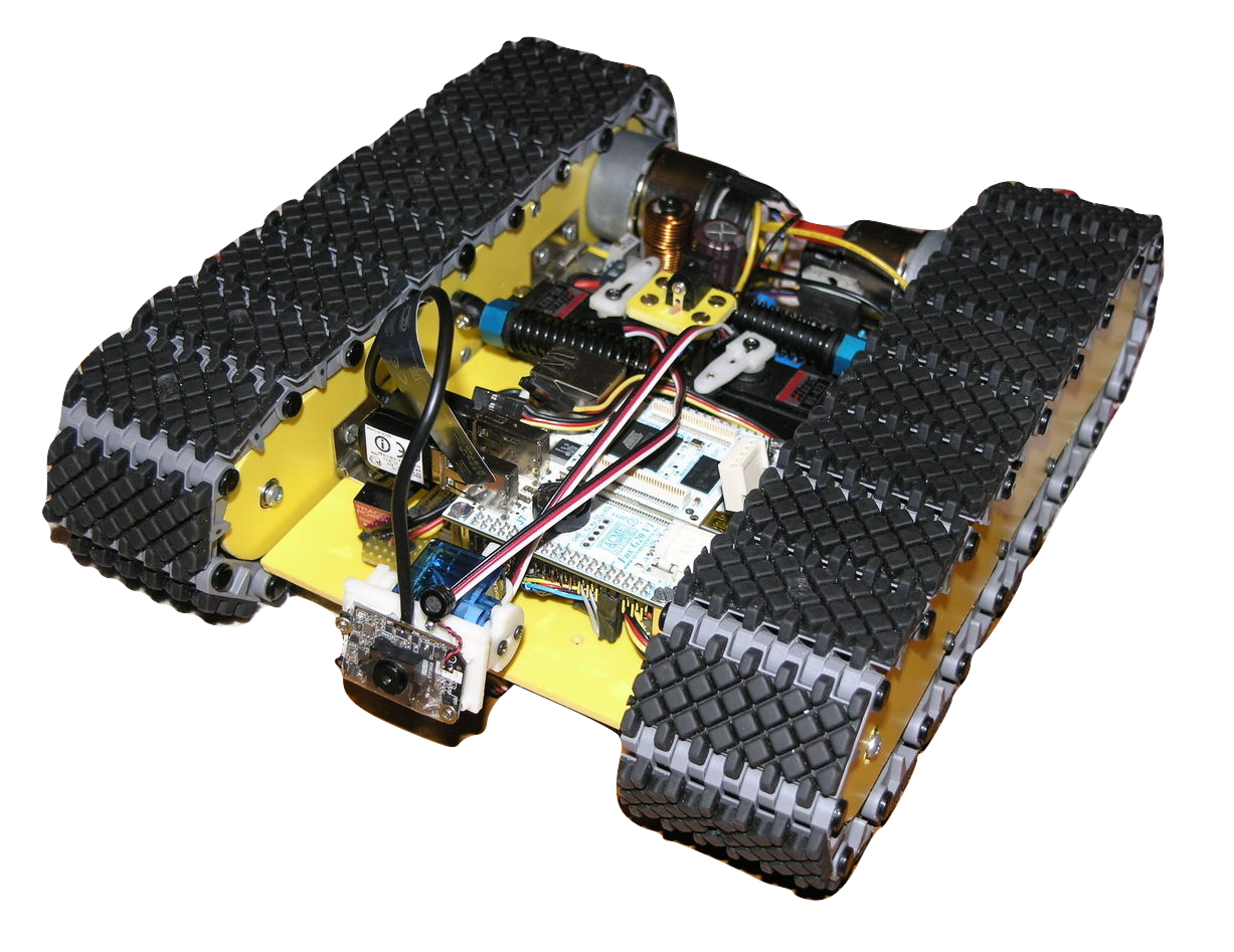
The ARVI project is an activity during three years. The first release of the robot started with only a short track (with a length of 25cm) from a first release with only two tracks and a first release of hardware works only with a remote control and have different problems to cable routing inside the chassis, this version was used only to test the angle of attack about the tracks and the dumper system to absorb the vibration when ARVI sliding inside the chamber.
The first stable release of robot was built without a cover, but compare with the first one was solved all problems about the cable routing, upgrade the embedded mini computer with a more powerful board and all programs was switched in the Robotic Operative System (ROS) framework.
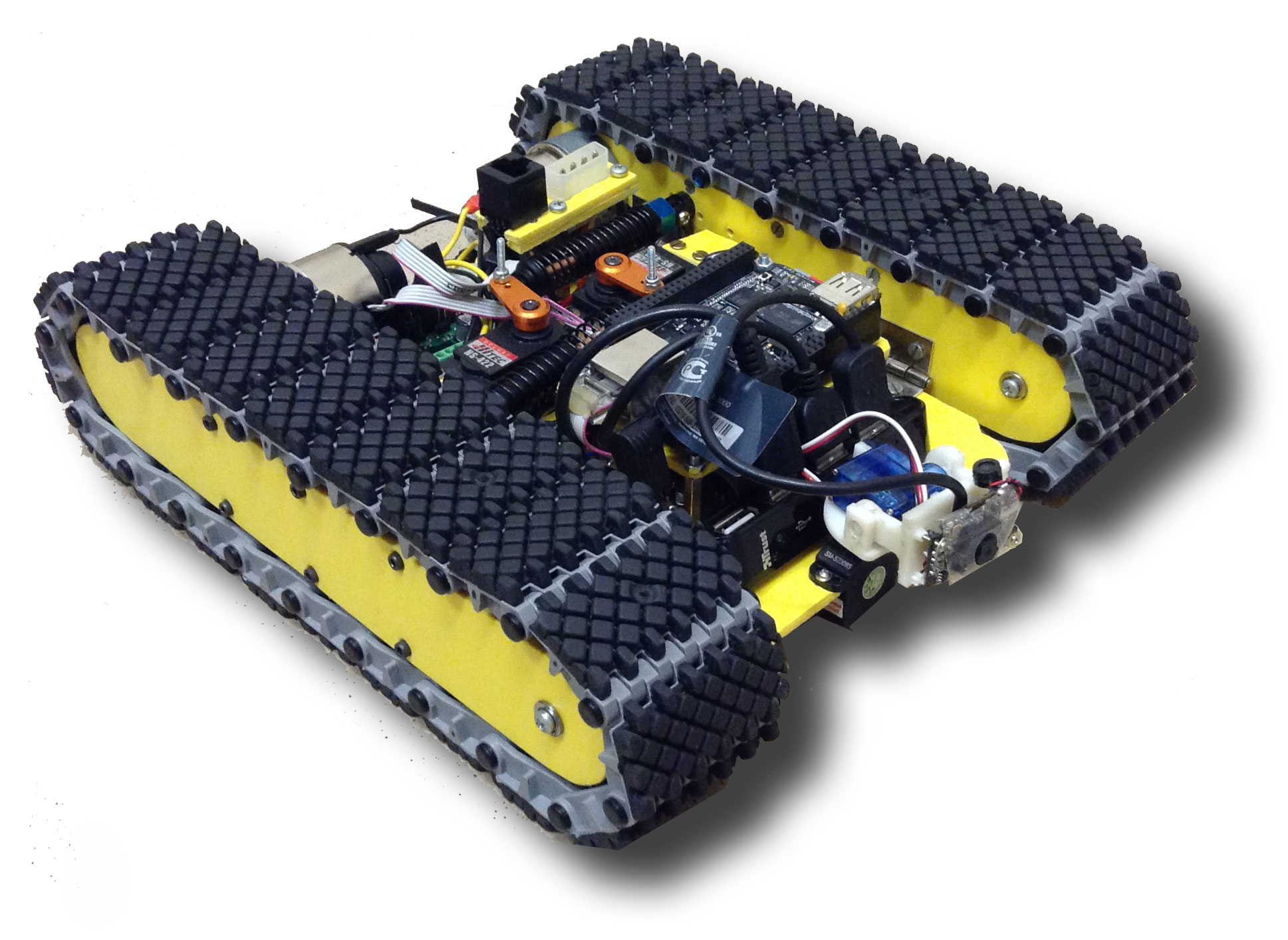
Last release of ARVI was totally redefined to include a tile pick up and a new improved hardware system to collect all information from two camera, one to see inside the chamber (in front of the robot) and a second one (inside the piston) to see below the robot.
The last release of the mobile platform has a new length of 28cm and a cover to protect all electronics components inside the robot.
Specification
ARVI is a new approach for remote handling in Tokamak maintenance. In the next section we speak about three different version about di mechanical platform. This robot with a low height from ground.
Finally the new robot specification compliant with all FTU constraint are:
- Chassis The robot must have maximum height of 115.7mm compare to the with of FTU’s gate. The robot must have a form factor with low profile to reduce oscillation when this move inside the vacuum vessel. The mobile platform must use a tracks to cross all holes inside the chamber and the minimum length of track must have 390mm in according with FTU Tokamak parameter in table;
- Hardware The robot must have one ore more cameras to show the environment inside the Tokamak machine and a system to luminance all chamber. These cameras are suggested with a dynamic zoom. The robot can work alone or wire-guided. It can autonomously execute inspection operations This robot can recognize a tile fall and or broken;
- Fault The mobile platform must have a system to rescue system when the robot does not working or it is in fault. This system can move the robot to the starting gate when it have the wheel in stall. A supervisor controller must send diagnostic information about mobile platform;
- Tile recover (Optional in first prototype) The robot must have a system to pick up a tile and move inside the robot in a particular box to store one or more tile broken. A tile have dimension and size written in table.
Subsystems
The work presented has divided in different subsystem from Mechanics to communication and power. More focus about all mechanical system, in particular the dumper to absorb the vibration when the robot sliding inside the chamber and the mechanical system to pick up a tile. A detailed list of all subsystem are collected below:
- Mechanics and hardware all characteristics and specification about the robot chassis and all particular mechanical components designed on the ARVI robot.
- Sensors The problem of measuring motor parameters, such as rotor speed and absorption current from the motors and a global description for the vision system.
- Power and actuation This subsystem constituted by the power management system of the mobile platform, and the system of locomotion constituted by two DC motors.
- Communication and software In the last subsystem are discussed the communication between robots and an external computer or tablet. An overview of all protocol in function inside the robot and all software to control or remote control the robot.
Mechanic and hardware
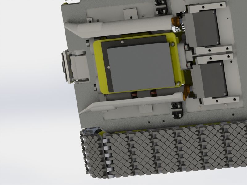
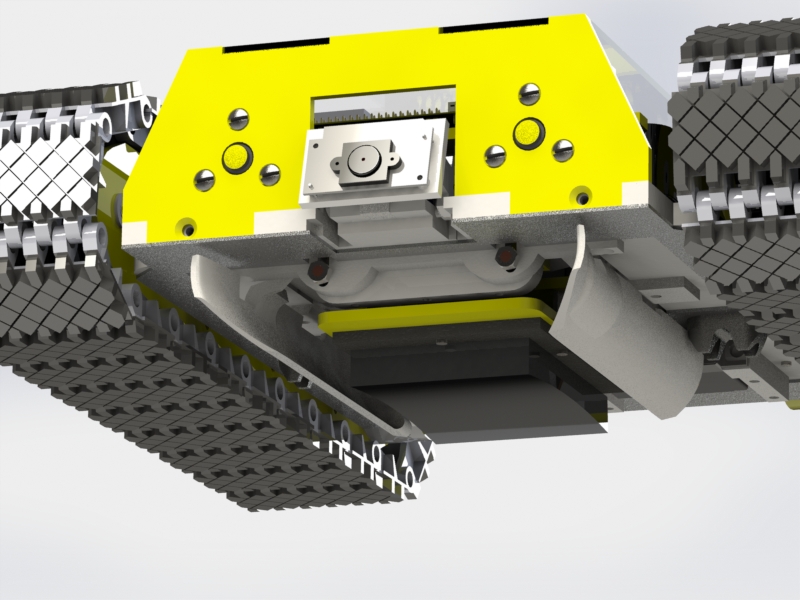
The chassis in order to ensure proper adhesion to the inner surfaces of the toroid, is divided between the two tracks and a central frame with all electronics components and a system to pick up a tile. The overall structure mechanics is designed and verified through the design software SolidWorks mechanics, developed by Dassault Systèmes, the rendering of ARVI robot is in figure below.
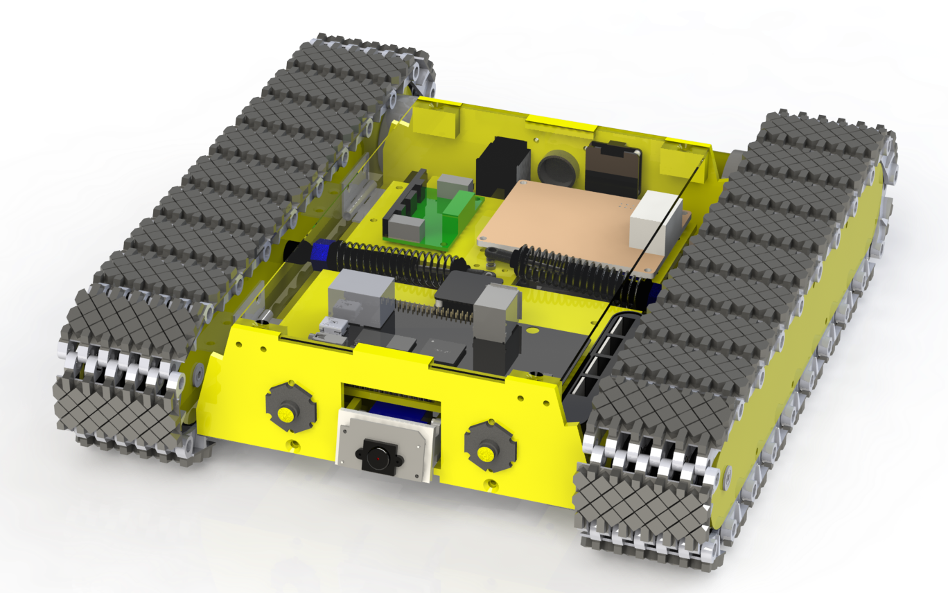
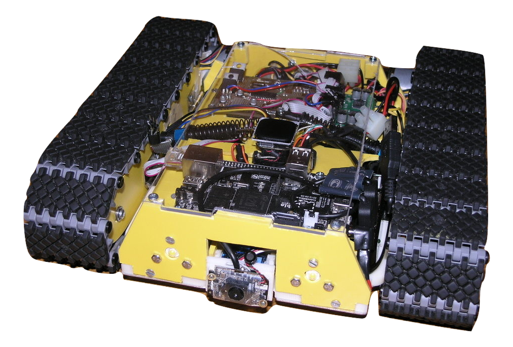
The design of the electronics of low-level Eagle has employed a specific software for the design of electronic circuits. The support of the camera, which assure handling and the base frame is designed by SolidWorks and realized through the 3D printer “uPrint”. The final prototype as a same look like from rendering and is in above.
The robot is divided in three parts, two specular tracks and a center frame.
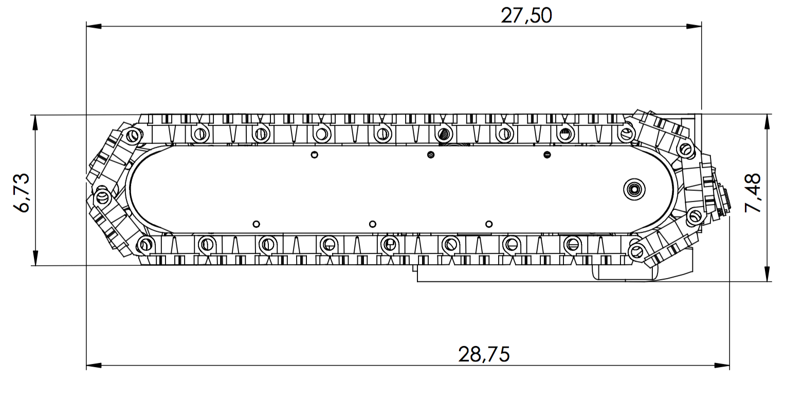
The mechanical system as built with two tracks with size of 4 cm plastic material in ABS. These are materials suitable to a prototypical embodiment, but changes can be provided in the realization of the final product.
As already said, to ensure a greater adherence to the surfaces of the toroid, the two tracks are independent and are linked by an active system which, possibly remotely, it changes the relative alignment.
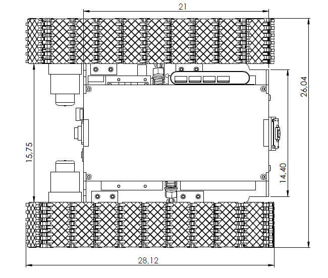
In the table below are collected all information about the ARVI platform and the information about dimension of tracks and the central frame.
| ARVI | value | dim. |
|---|---|---|
| width | 28 | cm |
| depth | 26 | cm |
| height | 7 | cm |
| tracked length | 28 | cm |
| tracked thickness | 4 | cm |
| base frame width | 14.40-15.75 | cm |
| base frame depth | 21 | cm |
Spring subsystem
The ARVI platform use to damping all vibrations when the robot move inside the chamber a spring subsystem. This subsystem is in figure below is assembled between the central part of the robot and the track system.
The Track is assembled with an hinge and can be rotate changing the angle of attack, this is required to move in the Tokamak chamber. For each Track, near the hinge is assembled a damper as in figure below.
The equilibrium forces between the plane and the central parts are expressed in the schematic figure below.
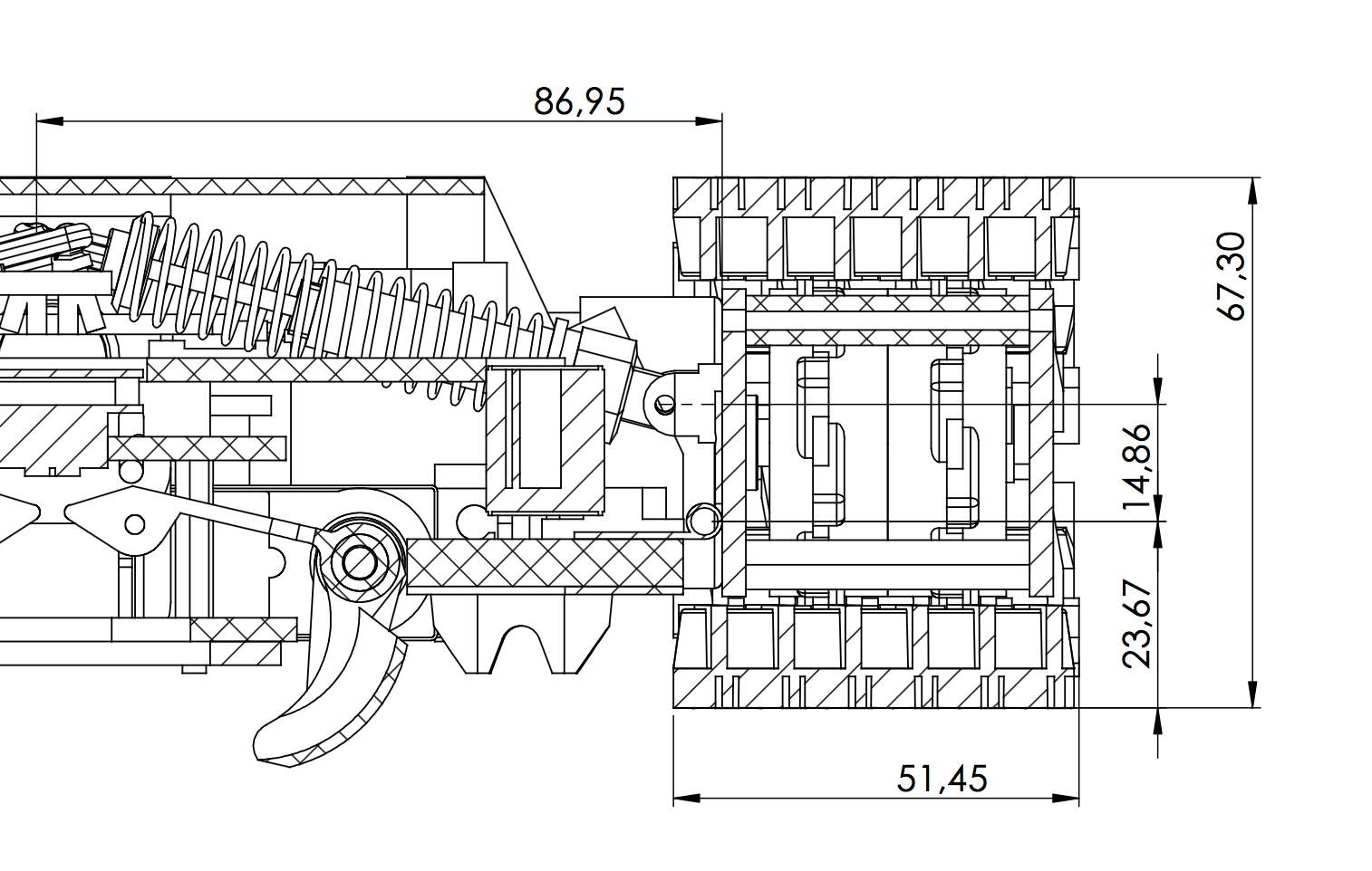
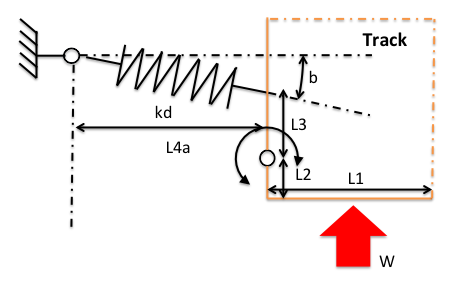
In a equilibrium of forces we have a force from the plane called $W$ push up the Tracks, a compress from the damper. The length is $L_{4a} = 86,95mm$ and is over the plane with a sum of $L_{2} + L_{3}$. The measure respectively for $L_{2} = 23,67mm$ and $L_{3} = 14,86mm$. Finally the surface of the Track $L_{1} = 51,45mm$.
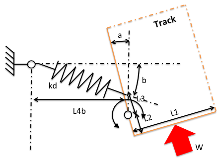
When the robot move in a curved surface the track can change the angle of attack, as in figure \ref{fig:suspension-compressed} and the equilibrium of forces can be expressed with the equation below.
\[k = \frac{W}{2} \frac{L_{1}}{L_{4a}\delta}\]With this information is be possible to find a good spring damper for the robot.
Tiles pick-up
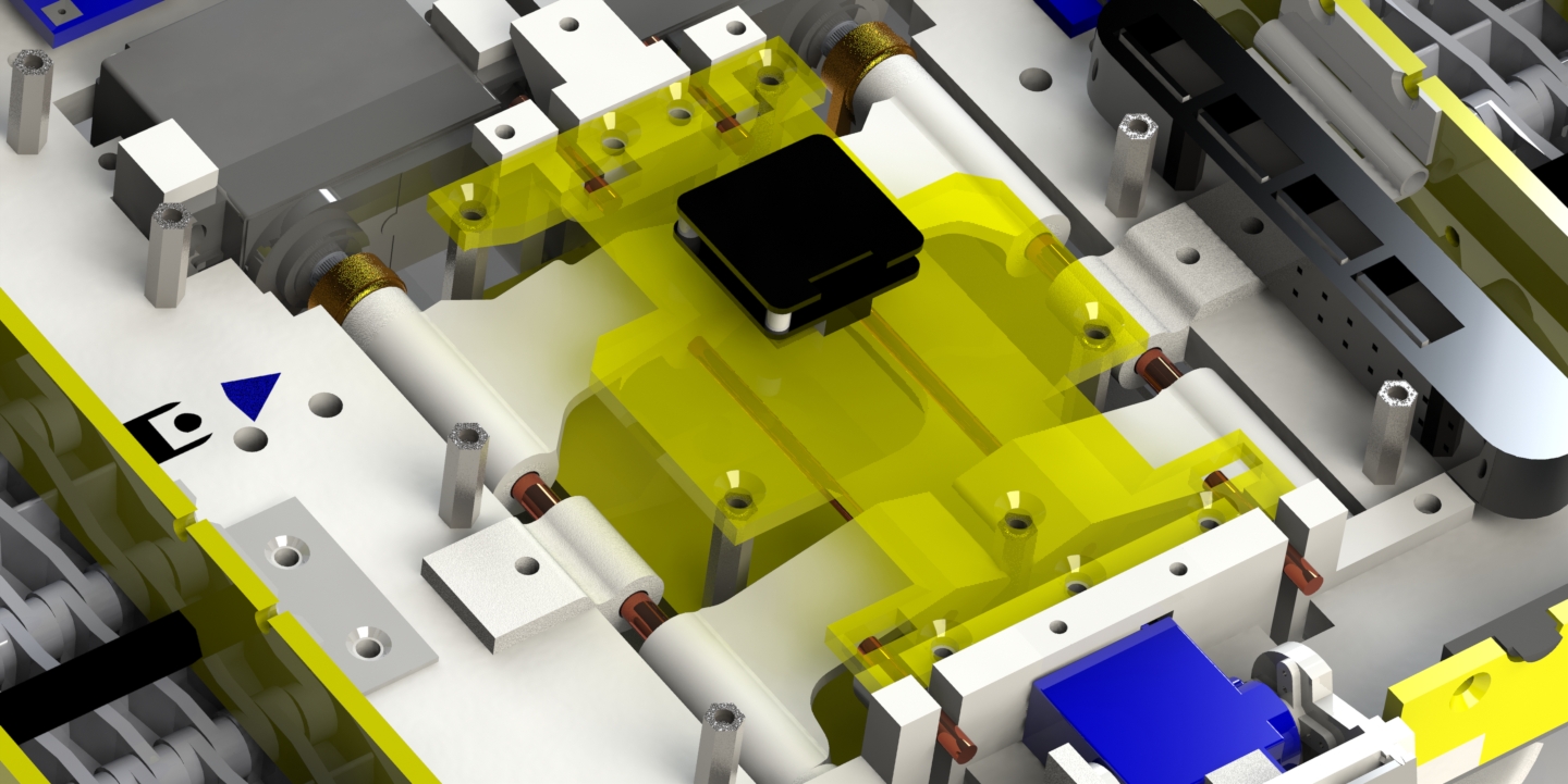
ARVI have a mechanical subsystem to pick-up a broken tile, with two blades and a piston moved by cam. The blades are actuated by two servo commands. These blades have a particular shape to bottleneck, when the robot approach a tile, passive align the sides tile’s. An overview of this subsystem is in figures 5.9.
In the first figure is show the system when the blades is opened and the tiles is approached, at this time the stick have attached the tile and it is possible to move up the piston plane. In figure is show the front view of ARVI and a strange
The piston move up and down with a four white brackets. This system with a cam mechanics push the piston frame down, at the same time, the blades open, as in figure and can be approach near the broken tile.
Sensors
It was chosen a high definition camera USB, it is produced by Logitech HD camera marketed by Microsoft LifeCam the 3000HD. To reduce the space on the platform is mounted without the protective.
Another camera is used for show the tile behind the piston. This camera is required to the technician and for the controller to complete a good placement the robot over the tile.
Power
The subsystem “Power management” consists of a system of a AD-DC power regulator, derivation of PC power supply. A switching regulator mounted on the “Reg Board”, the category of DC / DC converters, in figure 5.13 ensures the correct supply of energy to all the various tics electronic component, except for motors that are powered by the “H-Bridge” discussed later. This choice is better in comparison to the use of a linear regulator, which dissipate a higher power than that required by the platform.
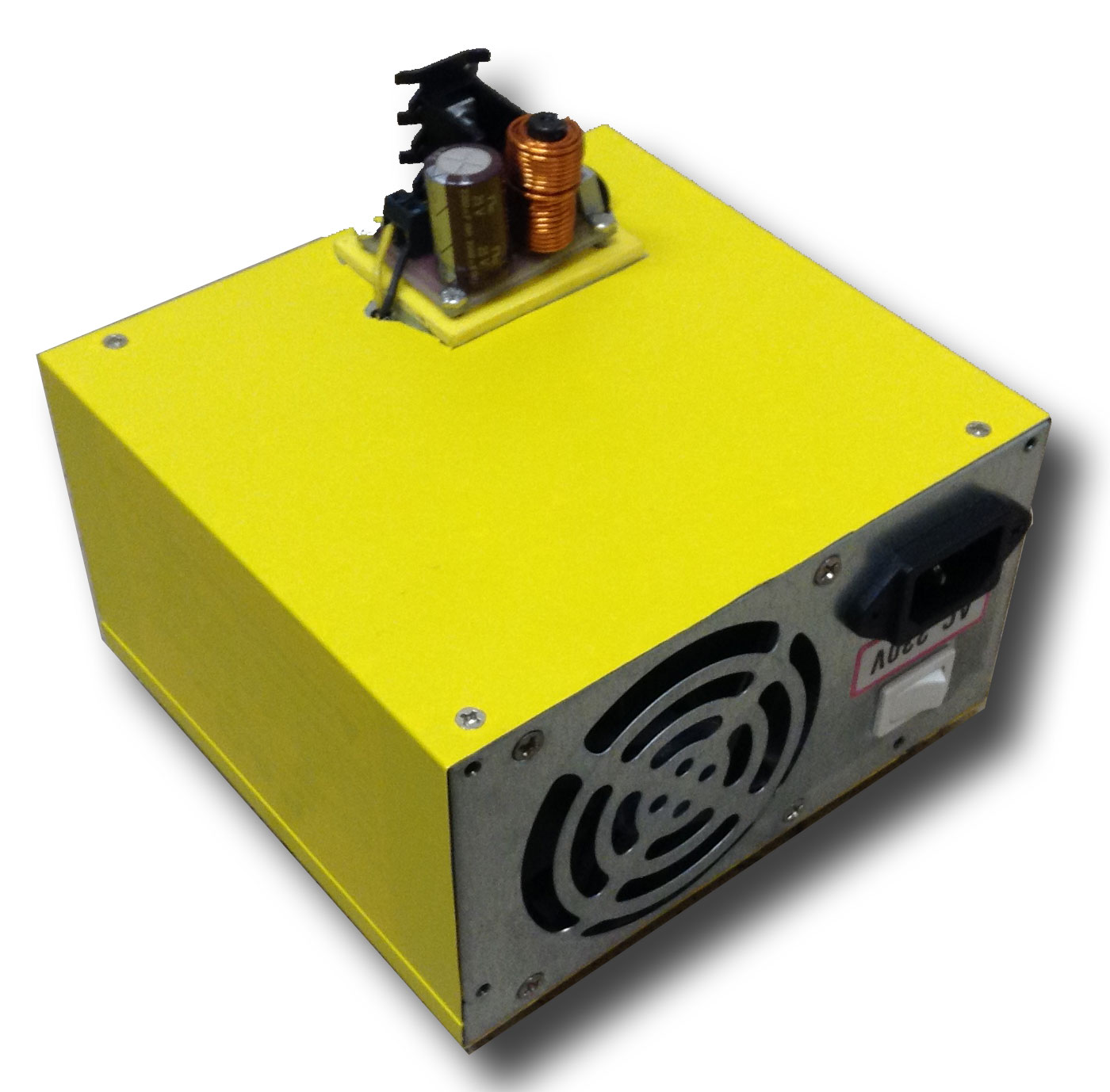
The advantage of this technique is to reduce drastically the power dissipated by the limiter circuit, compared to the use of controlled by analogic transistor. In a PWM (Pulse With Modulation), the transistor in an instant leads completely, minimizing the fall at its ends, or does not conduct, cancelling the current, and in both cases the power dissipation is minimal. In such a regulator output, requires a passive filter-type LC (such a filter is actually LRC with the resistance constituted by the conductor of the inductance of a few ohms) in order to obtain a signal the linear as possible to the heads of the other devices on the mobile platform. References in the literature on the design of power supplies. It is used for the switching regulator integrated produced by the National LM2576, which has the small size and the features necessary to meet the specifications of the project. The low pass filter has been realized with an inductance of $L = 20\mu H$ and a capacitor $C = 100\mu F$.
Actuation
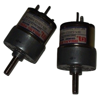
The tracks have moved through the motors which allow a good relationship velocity-torque output. Consumption is particularly low for the usual schemes work the robot, of the order of 400 mA - 600 mA at maximum voltage of 12V. The velocity that the engine may reach is about 170 RPM with a load of about one pound, then equivalent to about 17 rad / s.
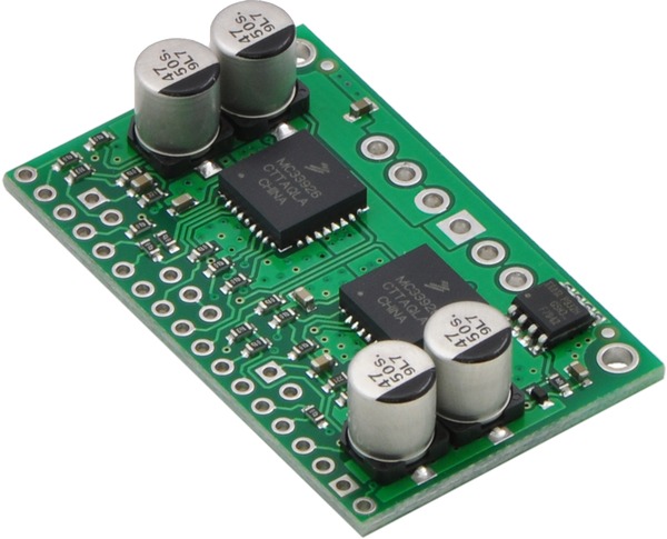
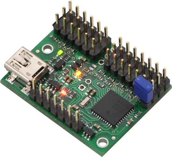
The Motor Drivers produced by Pololu is as an adapter of power and allows to move the motors for both directions of rotation, consists of two integrated circuits that drive each a motor. Each integrated circuit is constituted by four transistors that “acting as switches”. This card is the interface module between the control board and the engines.
PWM signals generated by the card Motion Control are “transformed” into power signals useful in handling the thrusters. In order for this to be possible, and the integrated MC33926 manages the current supply to the motors. The maximum current is 5A and 3A peak constantly; The card works with a power supply voltage between 5 and 28V.
The integrated “MC33926” operates with PWM signals with a logic level or 3V or 5V at frequencies from 20kHz to 20MHz; in the specific case it is selected a logic level of 3V at a frequency of 20kHz. The device is equipped with an internal feedback current and a protection system for under-voltage, over-current, and over-temperatures.
The Mini Maestro card is a card of the second generation of USB Servo Controller Pololu category. This card is a “servo-controller” very versatile with pin I / O general purpose.
Supports three modes of communication: USB for direct connection to the computer, TTL serial for use with embedded systems and finally an “internal scripting” a storage system of actions to be followed by the servo. For the prototype it is been chosen by USB communication.
The channels can be configured as servo outputs for use with standard RC servo by model or with the ESC (electronic speed control), such as digital outputs, or even as analog inputs. The signal for the servo high-resolution extremely precise, with a jitter of less than 200 ns, makes this servo controller is particularly suited to the platform.
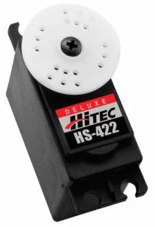
The integrated control of velocity and acceleration of each channel makes it simple to get movimentaciones “soft”. In this prototype is used for the movement of the pan-tilt of the camera and for controlling the attitude on the tracks.
Communication and software
The mobile platform ARVI implements various software running directly on-board computer and an application interface of the drive commands from keyboard and joystick is finally been also developed a version for the help with the tablet. The program present on the robot redirects commands from the external PC and sends commands respectively to the motion control as regards the handling of tracks or to the Mini Maestro as regards commands to be sent to servo controls. Inside each is implemented feedback control that ensures the achievement of the desired locations or speeds.